Project Overview :
● A self-driving vehicle, also known as an autonomous vehicle or rover, is a vehicle that is capable of traveling without human input.
● The vehicle will keep measuring the distance of the objects surrounding that using Lidar. The drive itself based on the measurements.
Requirements :
● Raspberry Pi 3 Model B+ .
● L298N Motor Driver Module.
● LM2596 DC-DC Buck Converter Step Down Module.
● DC Motors and chassis.
● Battery .
● YDLIDAR X2.
Initial setup for RPI-TENSORFLOW :
📚 Click Here , for the initial setup
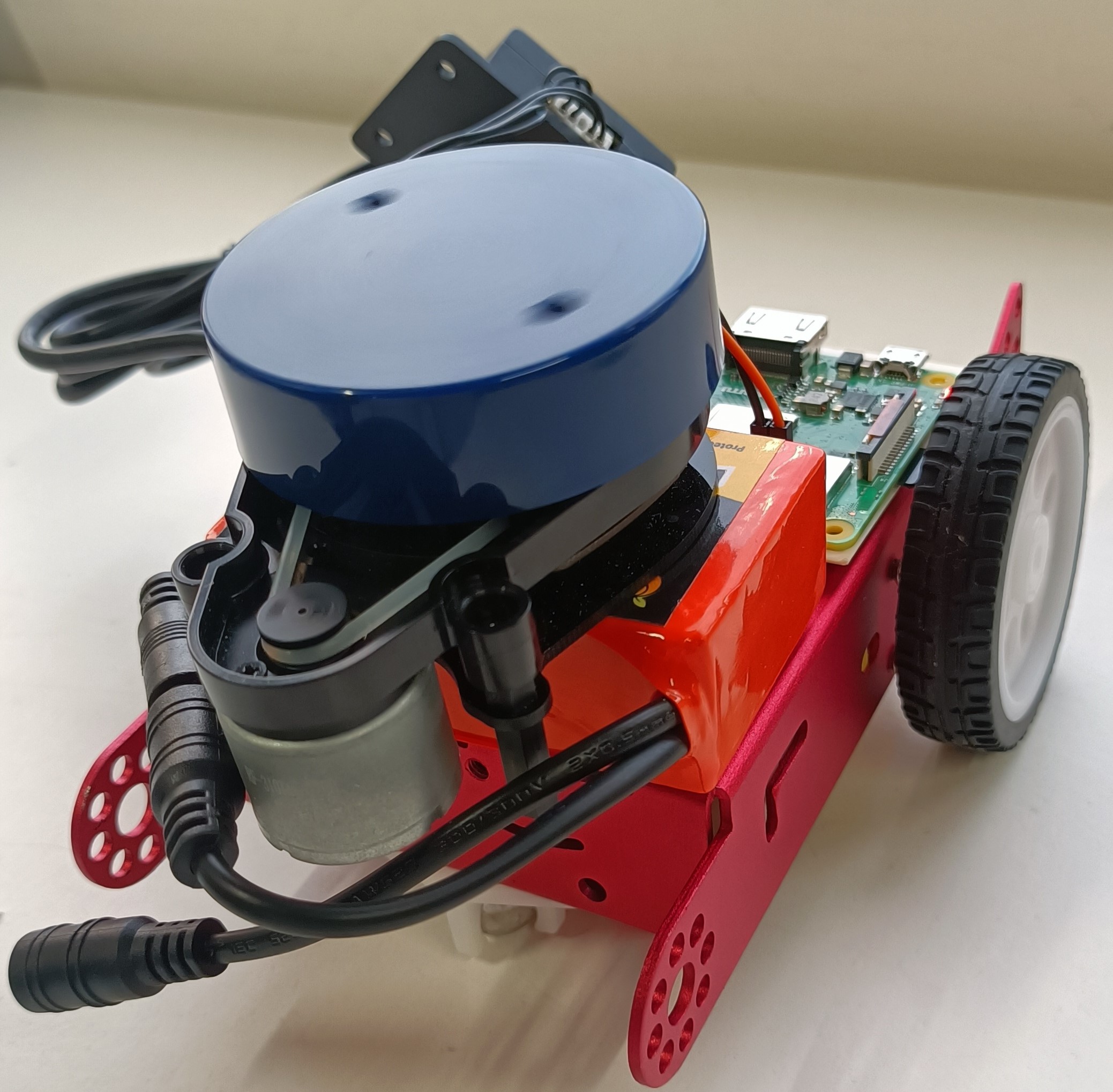
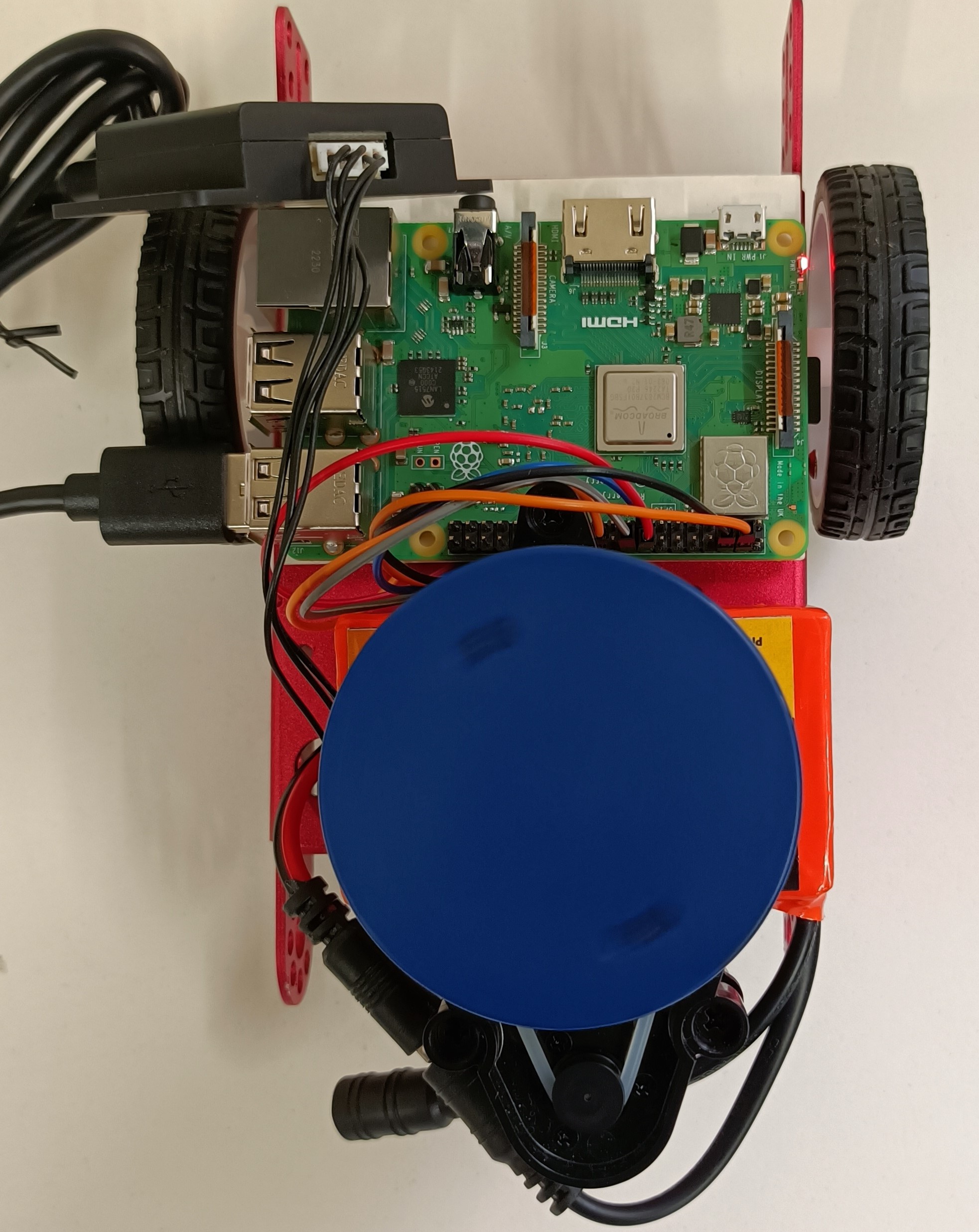
Here is the image of rover,
Circuit connection :

CONNECTION TABLE :
| RPI | I/O | Components |
|---|---|---|
| 5V | OUT + | Buck converter |
| GND | OUT - | Buck converter |
| BATTERY | 12V | L298N H Bridge |
| GND | GND | L298N H Bridge |
| GPIO12 | ENA | L298N H Bridge |
| GPIO22 | IN1 | L298N H Bridge |
| GPIO23 | IN2 | L298N H Bridge |
| GPIO24 | IN3 | L298N H Bridge |
| GPIO25 | IN4 | L298N H Bridge |
| GPIO27 | ENB | L298N H Bridge |
SPECIFICATION :
Raspberry Pi 3 Model B+
The Raspberry Pi 3 Model B+ is the latest product in the Raspberry Pi 3 range, boasting a 64-bit quad core processor running at 1.4GHz, dual-band 2.4GHz and 5GHz wireless LAN, Bluetooth 4.2/BLE, faster Ethernet, and PoE capability.
The dual-band wireless LAN comes with modular compliance certification, allowing the board to be designed into end products with significantly reduced wireless LAN compliance testing, improving both cost and time to market.

● Processor: Broadcom BCM2837B0, Cortex-A53 64-bit SoC @ 1.4GHz .
● Memory: 1GB LPDDR2 SDRAM.
● Connectivity: 2.4GHz and 5GHz IEEE 802.11.b/g/n/ac wireless LAN, Bluetooth 4.2, BLE Gigabit Ethernet over USB 2.0 (maximum throughput 300Mbps) 4 × USB 2.0 ports.
● Access: Extended 40-pin GPIO header.
● Video & Sound: 1 × full size HDMI, MIPI DSI display port, MIPI CSI camera port, 4 pole stereo output and composite video port.
● Multimedia: H.264, MPEG-4 decodes (1080p30); H.264 encode (1080p30) OpenGL ES 1.1, 2.0 graphics.
● SD card support: Micro SD format for loading operating system and data storage.
● Input Power: 5V/3.1A DC via micro USB connector, 5V DC via GPIO header, Power over Ethernet (PoE)–enabled.
YDLIDAR X2 :
● The simplest way to use the YDLIDAR X2 with a Raspberry Pi is to interface through the USB adapter.
● Connect a USB cable on the Raspberry Pi and then plug the other end into the YDLIDAR X2 USB adapter board.
● The YDLIDAR X2 Lidar is a 360-degree two-dimensional distance measurement product.
● This is based on the principle of triangulation, and is equipped with relevant optics, electricity, and algorithm design to realize high-frequency and high-precision distance measurement.
● While the distance is measured, 360 degrees of scanning distance measurement is achieved by continuously obtaining the angle information through the 360-degree rotation of the motor.
1. Scanning angle: 360°
2. Scanning range radius: 8 m
3. Ranging resolution: 2%
4. Scan frequency: 5-8 Hz
5. Sampling rate: 3000 Hz
6. Max current: 500 mA
7. Laser wavelength: 775-795 nm
8. Laser power: 3-5 mW
L298N Motor Driver Module :
● The L298N Motor Driver module consists of an L298 Motor Driver IC, 78M05 Voltage Regulator, resistors, capacitor, Power LED, 5V jumper in an integrated circuit.
● When the power supply is less than or equal to 12V, then the internal circuitry will be powered by the voltage regulator and the 5V pin can be used as an output pin to power the microcontroller.
● The jumper should not be placed when the power supply is greater than 12V and separate 5V should be given through 5V terminal to power the internal circuitry.
● ENA & ENB pins are speed control pins for Motor A and Motor B while IN1& IN2 and IN3 & IN4 are direction control pins for Motor 1 and Motor 2.

● Driver Model: L298N 2A .
● Driver Chip: Double H Bridge L298N.
● Motor Supply Voltage (Maximum): 46V.
● Motor Supply Current (Maximum): 2A.
● Logic Voltage: 5V.
● Driver Voltage: 5-35V.
● Driver Current:2A.
● Logical Current:0-36mA.
● Maximum Power (W): 25W.
● Current Sense for each motor.
● Heatsink for better performance.
● Power-On LED indicator.
DC motor :
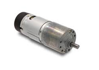
● A DC motor is any motor within a class of electrical machines whereby direct current electrical power is converted into mechanical power.
● High torque is the biggest advantage of using DC motors in robotics.
● The direction of current flow in part of the motor is changed periodically.
● The speed of a DC motor is controlled using a variable supply voltage or by changing the strength of the current within its field wind rings.
● While smaller DC motors are commonly used in the making of appliances, tools, toys, and automobile mechanisms, such as electric car seats, larger DC motors are used in hoists, elevators, and electric vehicles.
LM2596 DC-DC Buck Converter Step Down Module
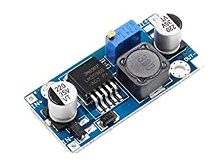
● Input: DC 3V to 40V (input voltage must be higher than the output voltage to 1.5v above cannot boost)
● Output: DC 1.5V to 35V voltage continuously adjustable, high-efficiency maximum output current of 3A
● Features: All Sanyo solid capacitors, the 36u thickening circuit boards, high-Q inductance with output value of high-power LED indicator.
Code :
We have to import Lidar x2 library. the file link : 👉🏻 LidarX2.py
import RPi.GPIO as GPIO
from time import sleep
import time
from LidarX2 import LidarX2

m1=22
m2=23
m3=24
m4=25
pwm1=12
pwm2=27
speed=70

GPIO.setmode(GPIO.BCM)
GPIO.setup(m1,GPIO.OUT)
GPIO.setup(m2,GPIO.OUT)
GPIO.setup(m3,GPIO.OUT)
GPIO.setup(m4,GPIO.OUT)
GPIO.setup(pwm1,GPIO.OUT)
GPIO.setup(pwm2,GPIO.OUT)
p=GPIO.PWM(pwm1,1000)
p2=GPIO.PWM(pwm2,1000)
p.start(speed-8.5)
p2.start(speed)

def f():
    GPIO.output(m1,GPIO.HIGH)
    GPIO.output(m2,GPIO.LOW)
    GPIO.output(m3,GPIO.HIGH)
    GPIO.output(m4,GPIO.LOW)
def b():
    GPIO.output(m2,GPIO.HIGH)
    GPIO.output(m1,GPIO.LOW)
    GPIO.output(m4,GPIO.HIGH)
    GPIO.output(m3,GPIO.LOW)
def l():
    GPIO.output(m1,GPIO.LOW)
    GPIO.output(m2,GPIO.HIGH)
    GPIO.output(m3,GPIO.HIGH)
    GPIO.output(m4,GPIO.LOW)
def r():
    GPIO.output(m1,GPIO.HIGH)
    GPIO.output(m2,GPIO.LOW)
    GPIO.output(m3,GPIO.LOW)
    GPIO.output(m4,GPIO.HIGH)
def s():
    GPIO.output(m2,GPIO.LOW)
    GPIO.output(m1,GPIO.LOW)
    GPIO.output(m4,GPIO.LOW)
    GPIO.output(m3,GPIO.LOW)
def lidar():
    lidar = LidarX2("/dev/ttyUSB0")  # Name of the serial port, can be /dev/tty*, COM*, etc.
    if not lidar.open():
        print("Cannot open lidar")
        exit(1)

    t = time.time()
    f=0
    g=0
    while time.time() - t < 5:  # Run for 20 seconds
        measures = lidar.getMeasures()  # Get latest lidar measures
        print(measures)
        time.sleep(0.01)
        print(str(len(measures))+" lenth")
        for i in range(len(measures)):
            a=str(measures[i])
            b=a.split(":")
            #print(b)
            c=int(float(b[0]))
            d=str(b[1])
            e=int(float(d[:-2]))
        #if c>=180:
            #print("0")
            if c<=180 and c>=175:
                print(e)
                f=f+e
                if e!=0:
                    g=g+1

    h=f/g
    print(h)
    lidar.close()
    return h
x=lidar()
z=int(float(x))
j=z-100
a=int(float(j*0.0116))
for i in range(a):
    f()
    sleep(0.5)
s()
y=lidar()
print(z)
print(y)
print(a)
OUTPUT :